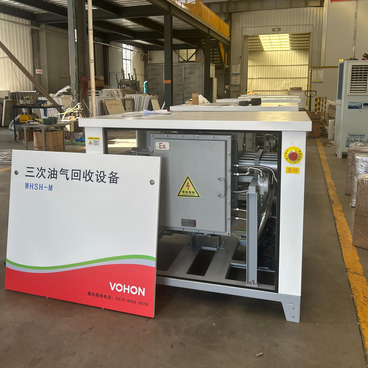
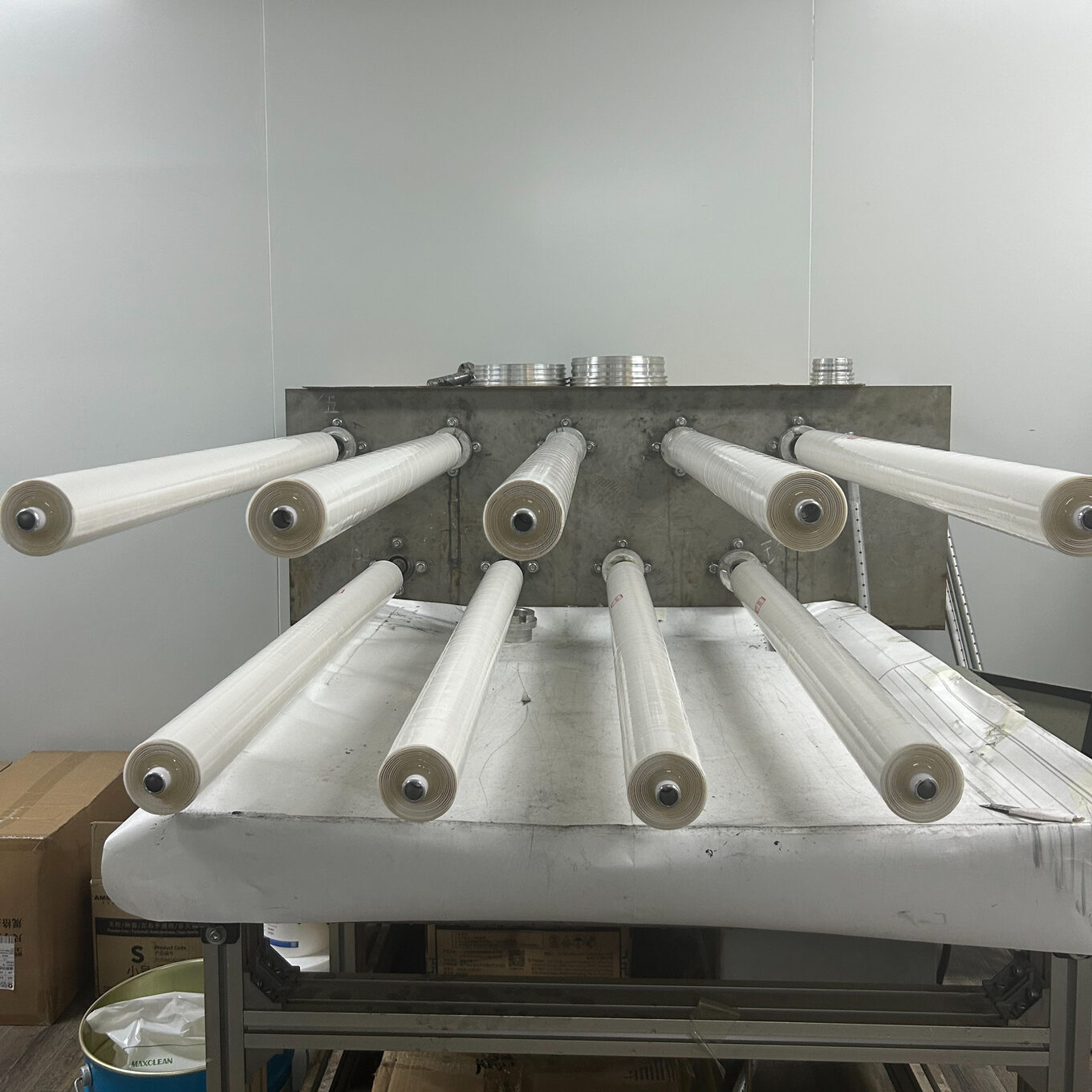
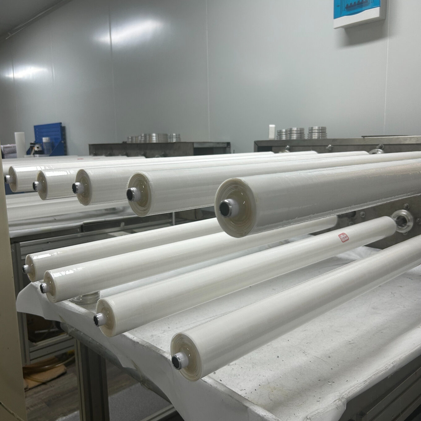
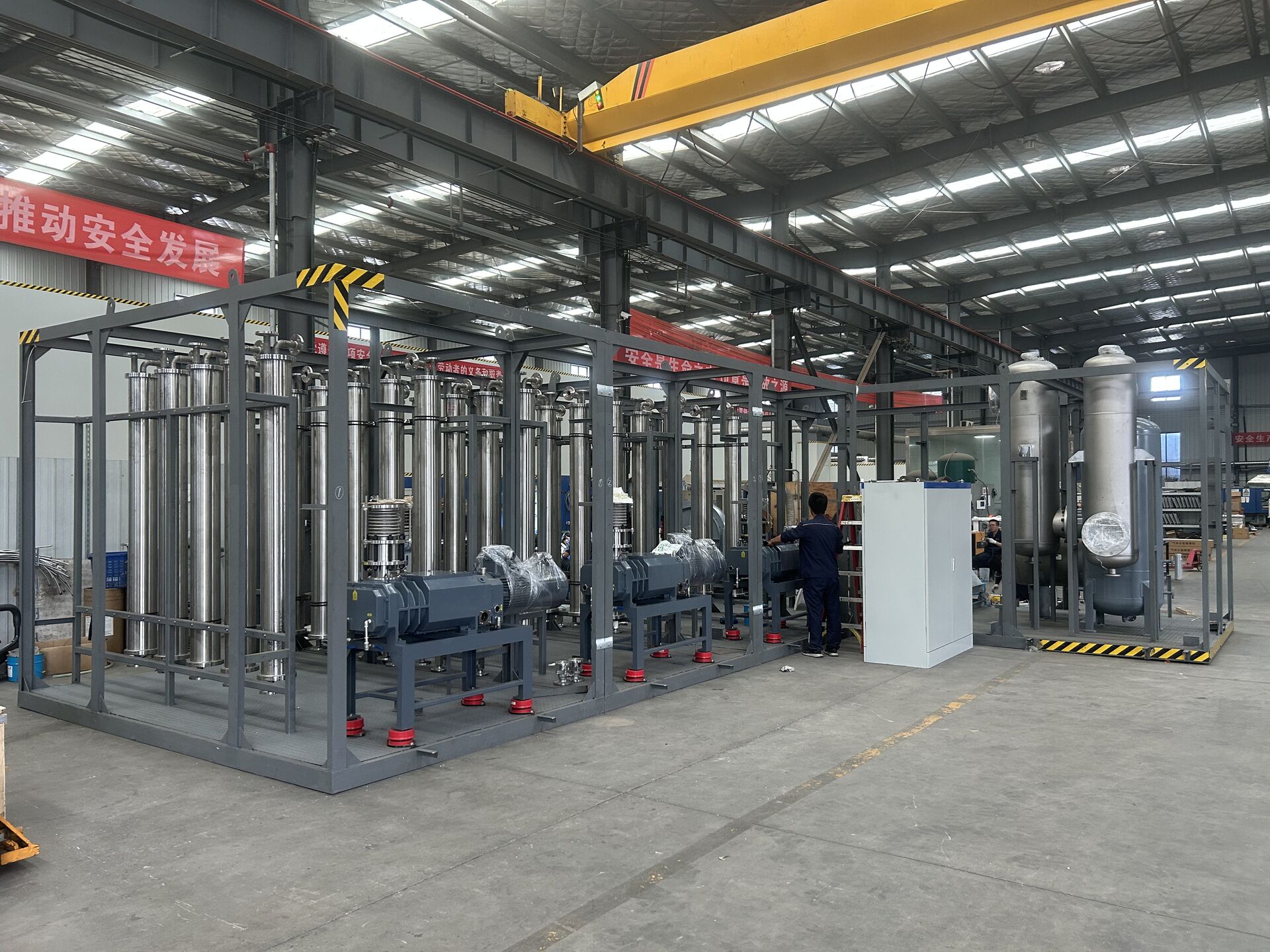
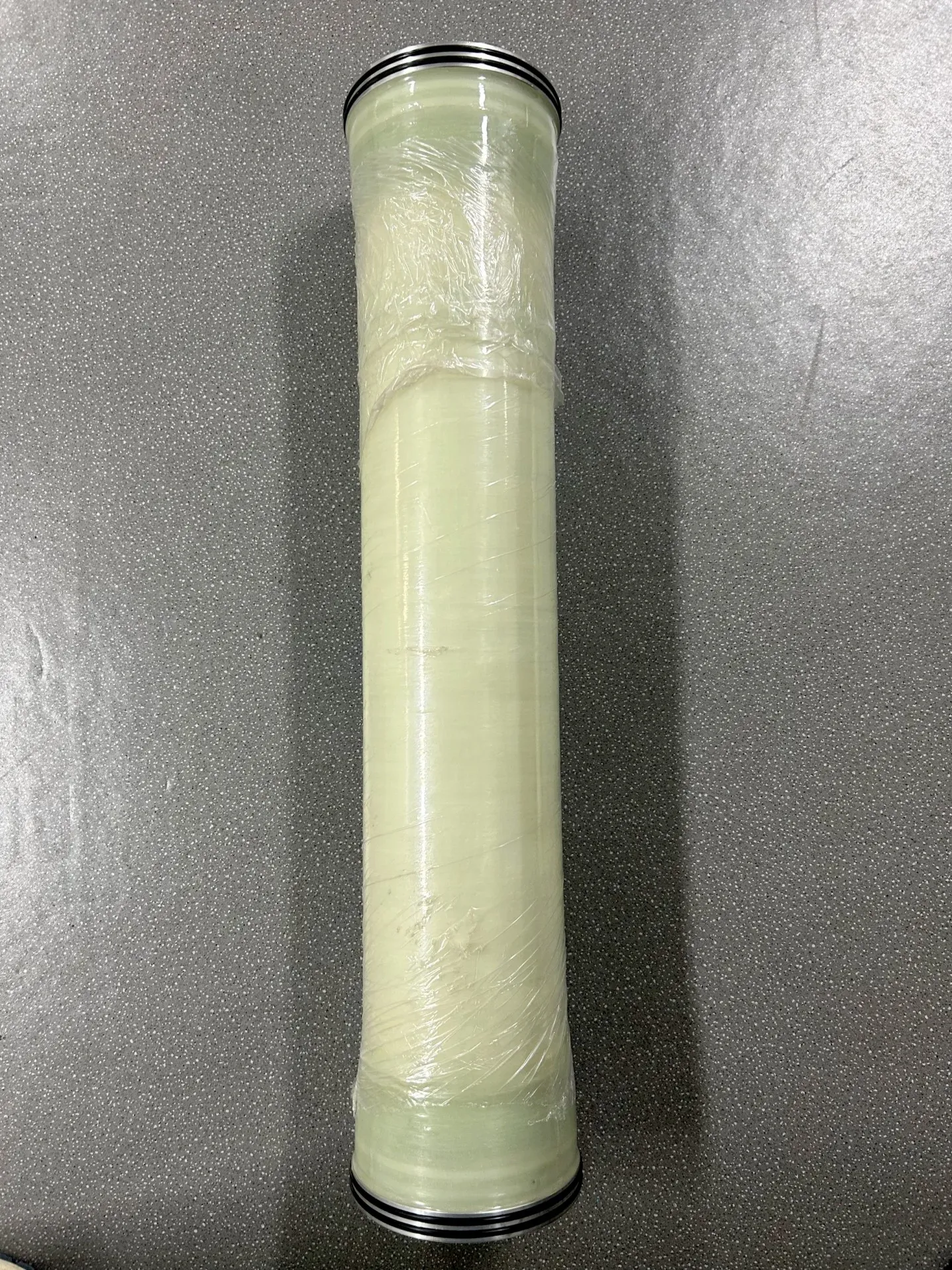
The membrane separation device is a continuous operation device, which is quite sensitive to the stability of the intake condition: the pressure fluctuates high and low, the pressure difference between the two sides of the membrane fluctuates, and the permeation and separation effect fluctuate accordingly; the flow rate is large and small, the membrane surface flow rate is unstable, and the pollution and concentration polarization accelerate in the fluctuation. The damage caused by fluctuation of working conditions is not one-time, but the life of the membrane is consumed over time-the same membrane, the device with stable air intake is used for a long time, and the device with chaotic air intake is attenuated in advance. This paper describes the path of working condition fluctuations affecting the life of the membrane, as well as the buffer configuration of steady voltage and steady flow.
The damage of fluctuation can be divided into three paths: first, pressure shock-the start and stop of the upstream pump and the opening and closing of the valve generate pressure pulse, which repeatedly impacts the sealing and supporting structure of the membrane module, and microleakage develops in the shock; Second, flow rate fluctuation-insufficient flow rate on the membrane surface during low flow rate, pollutants stay and deposit, and scouring during high flow rate period aggravates seal wear; Third, temperature drift-gas volume fluctuation is accompanied by temperature change, the membrane surface condition deviates from the design range, and the separation performance drifts. The superposition of the three paths shows that the flux decreases in advance, the pressure difference rises in advance, and the membrane life is discounted.
The buffer configuration is divided into three stages: the first stage is equipped with a buffer tank at the collection end-the collection main pipe to level the operation fluctuation, and the volume is checked according to the peak gas volume and fluctuation period; The second stage is at the booster end-the booster pump is equipped with frequency conversion control, which automatically regulates the speed according to the buffer tank pressure, and the outlet pressure is smooth to avoid frequent start and stop. The third stage is equipped with a stabilizing valve and temperature monitoring in front of the membrane unit inlet. The investment in the three-level buffer is not high, in exchange for the stability of the membrane working condition. This account should be included in the scheme stage, instead of being supplemented after the membrane decays in advance.
Working condition management depends on data: intake pressure, flow rate and temperature are transcribed daily, fluctuation amplitude and frequency are counted on a weekly basis, and fluctuation beyond the set interval is traceable to the source-check the upstream operation rhythm, pump control parameters and valve operation status. In scenarios with large differences between peak and valley values, consider staggered peak collection or grouping processing to allow the membrane unit to operate in a stable interval. The working condition data is still the basis for configuration optimization: whether the buffer volume is enough and whether the frequency conversion range should be expanded or not are all concluded from the measured data and are not changed by feeling.
There is another layer of working condition management that is easy to be ignored: working condition disclosure during shift change-peak period, abnormal fluctuation and disposal action of the previous shift, which is passed before the next shift takes over, and fluctuation disposal is not repeated or omitted. The working condition data is cut off from class to class, which is the common starting point for many "unclear causes" of membrane attenuation cases. The disclosure link has connected the cut-off.
| Hierarchy | Configuration | Function |
|---|---|---|
| Collecting end | Fluctuation of buffer tank leveling | Volume check by peak value |
| Pressurized end | variable frequency pump automatic speed regulation | Smoothing of outlet pressure |
| Pre-membrane | Temperature monitoring of pressure regulator valve | Cut only after reaching the standard interval |
| Data Management | Three parameters daily copy weekly system | Fluctuation traceability disposal |
| Scene processing | Staggering or grouping | Membrane running in plateau |
| disclosure mechanism | Working condition disclosure between shifts | Data is not broken |
According to the peak gas volume and fluctuation cycle check, taking into account the land occupation and investment.
Frequency conversion makes the outlet pressure smooth and protects the membrane. However, the frequency conversion range should cover the actual working conditions, and the long-term operation efficiency is low according to the lower limit. The parameters are set according to the measured flow range.
First check the upstream operation rhythm and valve opening and closing habits, and then check the control parameters of the pump and the gas storage in the pipeline. Most fluctuations come from the operation side, but there are few problems on the configuration side.
This article by LuoyangWohong PetrochemicalEquipment Co., Ltd. arranges that the company provides design, manufacturing and operation and maintenance services for condensation recovery, membrane separation recovery and complete solvent recovery devices for chemical and pharmaceutical enterprises. If you need process evaluation or scheme configuration, please contact and exchange.
Mr. Li 13526990215

Hotline